
PART I / ENGINEERING JOURNAL
01 / Why the Bridge was needed
A distributed LoRa network is useful only if its observations and messages can reach the systems and people expected to act upon them. We needed a permanent, serviceable boundary between our MeshCore network and the Atlas host, rather than a temporary development computer or handset acting as the sole interface.
The Bridge was intended to receive and send approved communications, provide local visual status, observe seismic activity through a WisBlock sensor and make selected health and event information available to Atlas. In its eventual architecture, the radio should be a genuine MeshCore network participant, while Atlas owns persistence, coordination, configuration and operator-facing interfaces.
Our first implementation demonstrated useful radio and host integration, but it also revealed that a LoRa modem controlled through a custom serial protocol was not the same thing as a native MeshCore companion.
02 / System architecture and its boundaries
The Bridge architecture separates four responsibilities:
- Radio and peripherals: the RAK19007/RAK4631 assembly, seismic module and local indicator electronics.
- Embedded firmware: native MeshCore participation and the device-side interaction layer as peripheral integration proceeds.
- Atlas serial owner: one persistent host process responsible for the USB Companion session and structured radio events.
- Atlas services: storage, configuration, operational status, the private Webviewer and the supervised publication pipeline.
The USB Companion has one serial owner. It maintains the device session and distributes structured events to the other Atlas services, preventing competing processes from opening the same port.
Guardian is the independent observer of this chain. Its design checks whether the host process is running, the USB link exists, the companion session is active, recent RF events are meaningful, delivery evidence matches the claim, and the website publisher is reporting fresh information. Those observations must be correlated: an active process alone does not prove a healthy radio path. When a failure is isolated, Guardian should identify the responsible layer, record the evidence and escalate or recover within defined limits.
Operational policy follows the same division of responsibility. Public-channel transmission is manual-only, with confirmation through the private Webviewer. CRUX-channel automation uses explicitly authorised rules. Routine mesh forwarding stays in the event stream; operator alerts are reserved for information that calls for attention.
03 / Industrial design: optical control and internal architecture
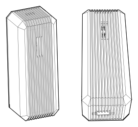
The industrial design question was not simply how to cover a development board. It was how to give Atlas a physical presence in a lived-in environment without creating another insistent appliance. The result is a compact, vertically oriented instrument: a dark, faceted monolith that keeps its electronics visually quiet and reserves its most expressive surface for deliberate status communication.
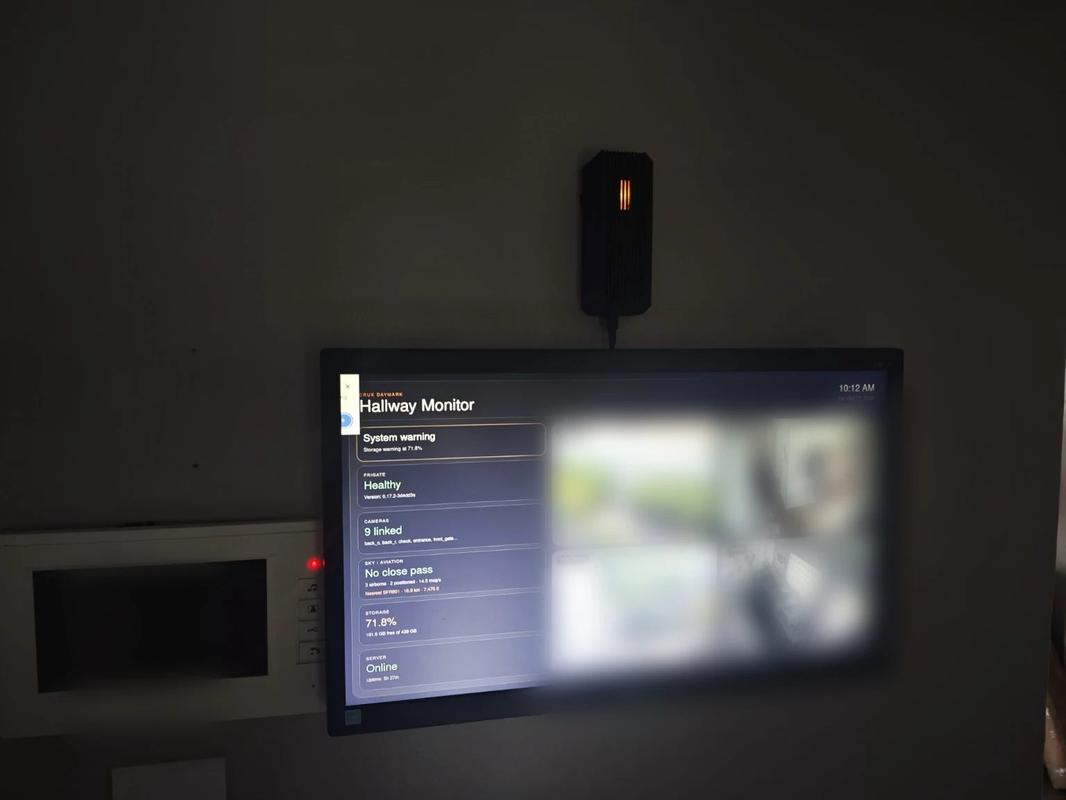
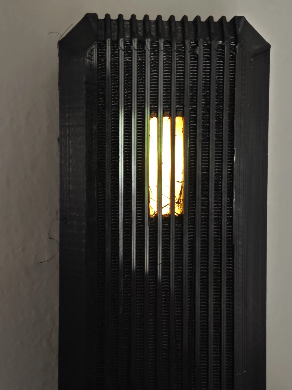
The vertical ribs are often read as heatsink geometry. In this prototype their especially important function is optical: they act as blinders around the narrow LED aperture, restricting lateral sightlines into the light source. The purpose is not to illuminate the room, but to make state legible primarily when an operator approaches and faces the instrument. The observed video demonstrates a narrow, luminous pattern set within an otherwise dark shell. A later controlled viewing-angle study will measure its effect in different ambient conditions.
This selective visibility translates Quiet Comms into geometry. A status LED placed behind a broad diffuser competes for attention from almost anywhere in the room. Here, much of that peripheral exposure is deliberately suppressed. The instrument remains available for inspection but does not constantly request it. Quiet does not mean invisible in a fault: the final design still needs escalation rules for urgent conditions that cannot safely rely on someone looking directly at the aperture.
The enclosure was developed around an approximately 120 × 40 × 40 mm internal packaging envelope. Beneath the shell, a purpose-designed resin tray forms the structural spine. The sled locates the RAK19007 WisBlock base, supports the separate LED PCB, organizes constrained cable and antenna routing, and defines how the assembly registers with the enclosure. This intermediate layer is why a compact form can remain orderly rather than becoming a tightly packed collection of loose modules.
Resin was useful during prototyping because printable geometry could be adjusted rapidly to match real component clearances, connector access and mounting relationships. It also provided an electrically insulating support for the assembly. The production-material review will assess thermal behaviour, fastener durability, dimensional stability and long-term servicing before the material specification is frozen.
The outer shell and inner tray are therefore designed as a coordinated assembly. The outer form defines silhouette, viewing direction and environmental interface; the tray controls alignment, retention and repeatable servicing. The USB cable exit, radio antenna path and any access required for diagnosis must be resolved without sacrificing the aperture’s optical control or placing conductive materials unnecessarily close to the antenna.
This is the CRUX approach to physical design: a visible silhouette supported by an invisible architecture of controlled tolerances, assembly sequence, electrical separation and meaningful interaction. The accompanying Rhino Make2D studies present assembled orthographic views, aperture sightlines, a PCB carrier study and an exploded arrangement to make those decisions inspectable.

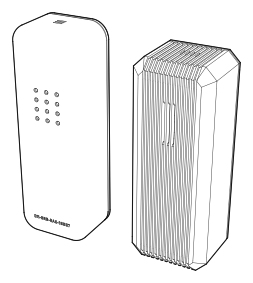

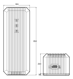

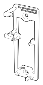
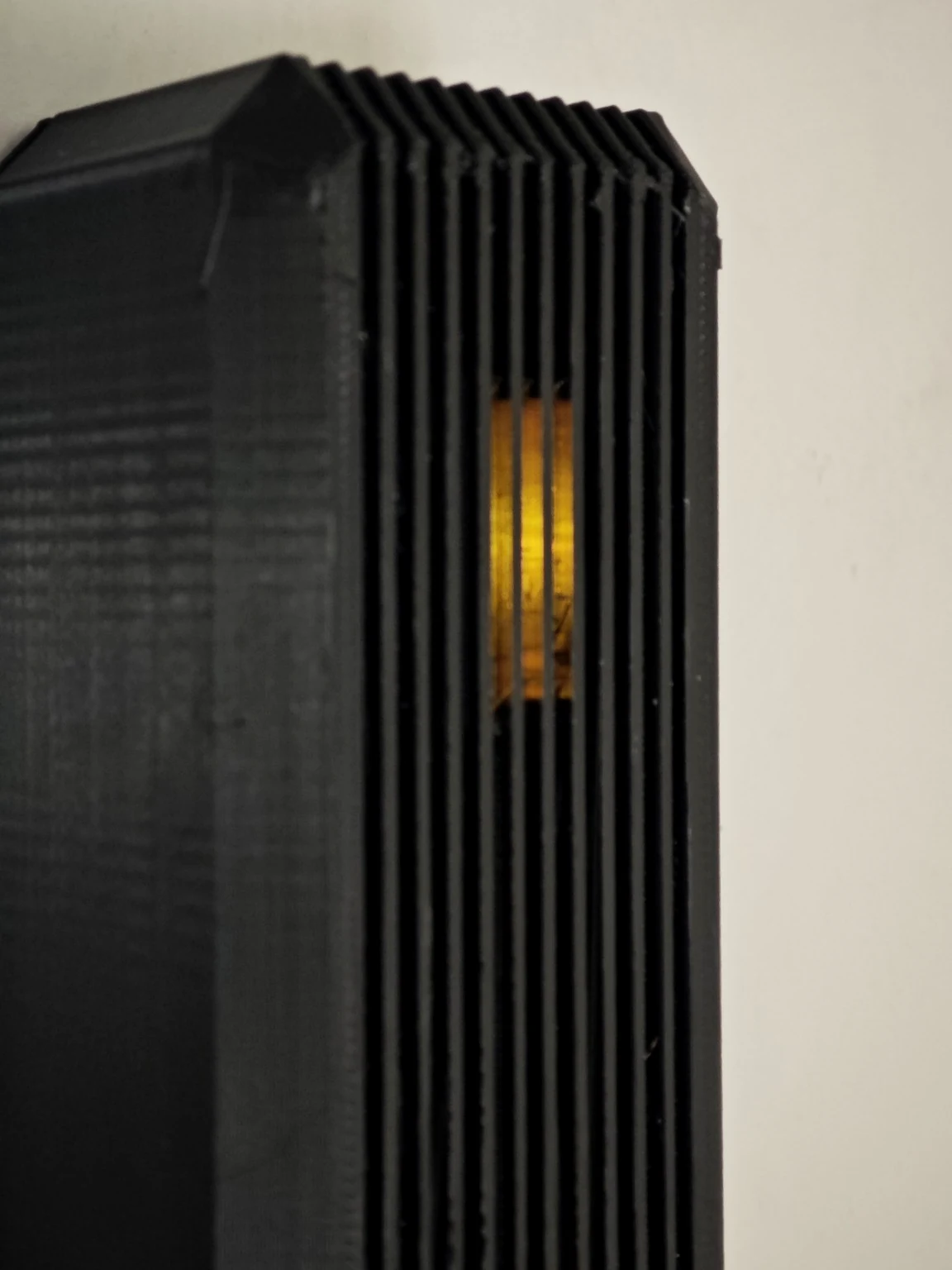
Design verification: light direction and assembly
The next optical verification exercise will compare front-on and off-axis viewing under matched camera exposure and ambient light. The existing rear and exploded CAD views document the wall-fixing interface and internal assembly; a physical fit check will confirm strain relief, fastener retention and antenna clearance. The supplied installed photographs already provide publication context.

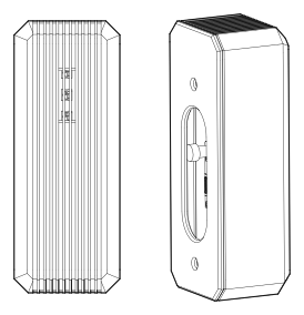

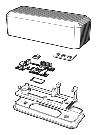
04 / Electrical design: packaging, light and sound
Electrical design followed the physical objective. The RAK19007 and EU868 RAK4631 provide the principal radio platform, while the RAK12027 adds vibration observations. The challenge was fitting radio, sensing and a deliberately narrow human interface into the mechanical envelope without treating lighting as an afterthought.
Our original WS2812-based visual experiment gave us a compact arrangement and a useful sweep effect, but it exposed a fundamental mismatch between expected and available supply conditions. At the prototype the anticipated 5 V supply was absent and approximately 3.25 V was measured. Rather than continue tuning animations around an uncertain electrical foundation, we revised the interface hardware.
The subsequent LP55231 workbench revisions established a more controlled baseline. Build 02-L resolved driver current-register initialization; later bench iterations demonstrated an amber heartbeat and RX/TX indication patterns. The next firmware acceptance pass will exercise these patterns during concurrent MeshCore activity and verify their timing and priority.
The LP55231 driver was selected to make current-controlled light output, finer brightness management and repeatable transitions part of the electronics architecture. The revised PCB separates the physical placement and management of the indicator from a direct-drive matrix assumption. Its design is inseparable from the aperture: no amount of firmware can compensate for uncontrolled spill light or a poorly placed emitter.
The CRUX visual language uses amber, yellow and coral-red to distinguish everyday states and warnings, with an ice-blue-to-white sequence reserved for exceptional safety signalling. These are design intentions requiring a definitive mapping to actual machine states; colour alone must not be the only indicator of severity. Our early tests established a functioning sweep but also exposed coarse fades, which informed subsequent refinements.
A RAK18001 buzzer was selected to add a second, audible information channel. Its role is to make selected direct messages, monitored contacts, node events and critical faults perceivable when visual confirmation is insufficient—not to react to routine mesh forwarding. Integration of the module, audio profiles, quiet periods and priority arbitration is scheduled as the next peripheral acceptance stage.
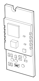
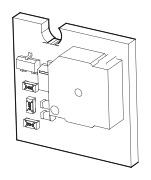
The electrical design must ultimately be documented as an interconnected system: voltage domains, driver current, shared interfaces, radio power integrity, peripheral connectors, PCB mounting and suitable cable routing. The custom LED PCB revision is a design decision whose cause, not merely its appearance, deserves illustration.


05 / Embedded logic: choreographing the physical interface
An enclosure can constrain light and a driver can source current, but neither specifies how the Bridge should behave. That requires embedded logic. The first deployment ran the RAK4631 on RUI3, with custom bridge behaviour and Atlas-side serial handling used to translate radio events into local state, communication and indicator actions. This made the first physical interface possible, even though the modem-based implementation later proved unsuitable as the definitive MeshCore architecture.
The intended firmware model is a small, explicit state machine. Radio, startup, degraded operation, maintenance, message attention and critical conditions should resolve into defined outputs rather than ad hoc LED commands scattered through the application. A change in system state selects a pattern; the animation layer then produces its light or sound envelope without holding the primary communications loop hostage.
For the LP55231, elegant transitions require choices about perceptual brightness, step size, sweep direction, fade duration and interruption. The prototype demonstrated a working sweep and revealed coarse fading. That observation now drives the next firmware iteration: measurable transition timing, nonblocking execution and predictable interruption by higher-priority events.
The same principle governs the planned RAK18001 patterns. Each audible event needs a bounded duration, priority, mute policy and a mechanism to pre-empt lower-priority alerts. Routine notifications must never repeatedly interrupt radio processing, while seismic and critical fault signalling must not depend on a user preference that silences ordinary message chirps.
This is the pre-host design boundary: essential local behaviour should remain interpretable when Atlas is not yet connected. The device must be able to indicate boot progress, local faults and a lost host connection using its own observations. Remote network health and message delivery belong to the wider Atlas evidence chain, where they can be confirmed independently.
The later migration to native MeshCore USB companion firmware changed the communications foundation. It did not eliminate the need for a CRUX-specific physical interaction layer; it made firmware integration more disciplined. Our design objective is to integrate LED, buzzer and seismic handling without compromising MeshCore timing or requiring a new firmware flash whenever an operator changes a routine contact notification profile.
Atlas server software will eventually provide persistent configuration, history, correlation and operator interfaces. That wider service architecture belongs to a separate CRUX software engineering article. Here the design focus remains close to the object: what its electronics sense, how its firmware decides, and what a human sees or hears.
A designed state machine, not a collection of effects
The peripheral acceptance test will combine radio reception, timed LED transitions, a queued notification chirp and an urgent override. It will measure communications continuity, execution latency, priority behaviour and the legibility of fault indications. These tests are the bridge between the specified state machine and field-ready indication.
06 / Deployment failures: what the logs really proved
Some transmissions were queued and accepted locally while the intended handset had not yet been confirmed as a recipient. That exposed a useful commissioning sequence: queue acceptance, serial write, transmit completion, mesh forwarding, recipient reception and explicit acknowledgement are distinct checkpoints. A message becomes a verified delivery only when the appropriate receiving evidence is recorded.
We also encountered serial-port availability and recovery problems, incomplete remote diagnosis, and inconsistencies between device state, website publishing and the operator’s understanding of the deployment. A node could be described as operational while critical parts of the chain were unverified.
The Bridge was placed in maintenance during the redevelopment. Rather than presenting that as failure of the entire design, the engineering decision was to preserve successful elements — the enclosure, radio hardware, event services and operational observations — while replacing the unstable or mismatched communications assumptions.
07 / Redevelopment: becoming a MeshCore member
The subsequent development work returned to a clean firmware baseline and a native MeshCore USB companion. Recovery work with a RAKDAP1 and SWD access provided a repeatable approach for rescuing or reflashing RAK4631 modules, documented separately in Engineering Log EL-001.
The replacement architecture treats the companion as the radio-facing participant and gives a persistent Atlas host process exclusive serial ownership. Atlas services consume its structured state and events rather than directly controlling the radio from multiple scripts.
The companion commissioning logs confirmed working connections and received messages. The next test set adds return-message acknowledgement, recipient-side confirmation, peripheral indication and recovery scenarios. Each result will be attached to the function it verifies so that the deployment record remains as useful as the build itself.
08 / Guardian commissioning status
At the 15 October 2026 service inventory, atlas-meshcore-guardian-v2.service was inactive. The native MeshCore USB Companion, CRUX automation gateway and private Webviewer were running, while the USB device remained visible to the host. That snapshot gives the Guardian work a concrete starting point.
The next commissioning stage is observe-only: bring Guardian online, compare process and USB status with session activity, correlate RF reception and publisher freshness, and test how stale or contradictory observations appear to the operator. Recovery actions will follow only after those checks behave consistently.
Subsequent drills will isolate one fault at a time—a stopped service, missing USB device, stale event stream or delayed status export—then verify escalation, bounded intervention and the evidence recorded after recovery. This keeps the supervisory logic measurable while the Bridge's local light and sound rules progress through their separate peripheral tests.
PART II / VERIFICATION & LESSONS
09 / The next acceptance boundary
The revised Bridge must be evaluated as a complete chain: physical power and electrical limits; companion persistence; selected channels and contacts; receive and send constraints; correct indicator and buzzer routing; seismic observations; Guardian recovery; and website telemetry integrity.
The first deployment and the redevelopment form one traceable engineering programme. Together they show how physical prototyping, firmware semantics, operations and human accountability influence one another. The strongest outcome is a better-defined architecture, supported by a clearer commissioning method.
The approved monochrome Rhino Make2D plates are included in this revision. The remaining release sequence covers electrical sign-off, peripheral acceptance, dated end-to-end delivery tests, publication-chain freshness and image privacy review. Planned or developing functions are identified beside the evidence that supports them.